The connecting rod group transmits the force experienced by the piston to the crankshaft into torque, and at the same time changes the reciprocating motion of the piston into the rotational motion of the crankshaft.
The connecting rod group is composed of the connecting rod body (connecting rod small head, shaft, connecting rod big head), connecting rod cover, connecting rod bolts, and connecting rod bearings.
The connecting rod bearing is subjected to the dynamic load of the impact cylinder combustion pressure and the inertia force of the piston connecting rod group in the work, and the relative sliding speed is high, so it must have high mechanical strength (fatigue resistance) and heat resistance (thermal hardness, thermal strength), and have sufficient friction reduction performance.
Common failure modes include spalling, melting, bonding, tearing, eccentric wear, and cracking.
Generally speaking, there are two main causes of connecting rod bearing breakage.
First, the quality defect of the connecting rod bearing:
The connecting rod bearing usually adopts forced lubrication, and the pressure lubricating oil forms a wedge-shaped high-pressure oil film with the relative movement of the journal and the bearing, which transmits pressure and exerts shear force to the bearing alloy layer, and these external forces alternate periodically with the operation of the diesel engine.
Second, bending fatigue leads to cracks in the alloy layer of bearings:
If the alloy layer is poorly bonded with the tile back to form a sandwich, the alloy layer will be subjected to severe impact by periodic variable loads, and microcracks will be generated due to excessive compressive stress, bending stress and fatigue, and then the microcracks will gradually develop into macroscopic cracks.
However, not all connecting rod bearings are caused by the above reasons, and the following analysis of the cracking of connecting rod bearings of a certain type of medium-speed diesel engine and put forward improvement measures.
1. Fault description
In 2018, a certain type of medium-speed diesel engine was found to have cracks and collapse on some connecting rod tiles during maintenance and dismantling, and there were indentations and collapses around the oil holes and oil grooves on the connecting rod body.
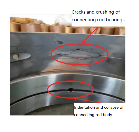
The service time of this batch of diesel engines is about 6000h, and the tile surface on the connecting rod that has not been crushed also has bright bands of local contact wear, and the back of the tile has traces of bending and deformation.
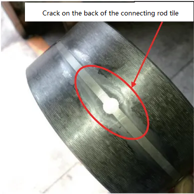
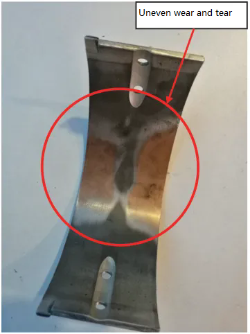
Also in 2018, cracks were found on the steel back of the tile on the rear connecting rod of the medium-speed diesel engine that was returned from the market for about 6200h, and there were traces of bending deformation and wear near the oil hole and oil groove on the back of the tile;
The wear of the tile surface is uneven, especially the corresponding parts of the oil groove and the oil hole are not worn due to the deformation of the back of the tile, while the wear of the oil groove and the outside of the oil hole is relatively heavy, see Figure 2 and Figure 3.
2. Analysis of the cause of the failure
(1). Connecting rod oil groove and oil hole structure
The piston of this type of medium-speed machine is free injection cooling, and the cooling oil is sent from the oil hole of the main journal of the crankshaft to the oil groove of the connecting rod small head bushing and the connecting rod small head nozzle, and then the small head nozzle is sprayed into the piston cooling oil cavity by the small head nozzle, as shown in Figure 4, and the red line in the figure is the flow trajectory of the cooling oil.
In order to introduce the oil from the oil hole of the crankshaft connecting rod neck into the oil hole of the connecting rod shaft, oil holes are arranged in the lower bearing of the connecting rod, the part of the upper bearing of the connecting rod and the connecting rod shaft, and the circumferential oil groove is arranged in the large head hole of the connecting rod.
The oil hole of the connecting rod shaft and the circumferential oil groove structure of the connecting rod large head hole are shown in Figure 5.

By consulting the product design manual, from the perspective of force, the connecting rod tile bears the main working load, so the connecting rod tile should not be arranged with oil grooves and oil holes;
Some tests show that when the bearing area of the bearing pad is the same, the bearing capacity of the bearing pad after arranging the oil groove and oil hole is only 1/4 of that without slotting, and the bearing capacity of the bearing pad is greatly reduced.
According to the oil film pressure distribution and axial trajectory of the sliding bearing, the position of the oil hole and oil groove should be reasonably arranged to make the oil supply smooth.
The oil holes and grooves should be opened in the area where the bearing load is low, so as not to affect the bearing capacity.
That is to say, the connecting rod bearing should be grooved and opened in the lower bearing, and if it is really necessary to groove the connecting rod tile, the high-load area should be avoided as much as possible.
The connecting rod body and connecting rod cover attached to the connecting rod bearing hole play the role of supporting the bearing pad for the bearing housing hole, and the oil hole and oil groove corresponding to the high load area of the bearing should also be avoided.
When there is an oil groove or a large hole on the surface of the housing bore, under the action of the bearing load, the wall surface will be concave downward due to the loss of support behind it, resulting in unfavorable bending stress on the back section of the pad.
At the same time, the wall at the edge of the depression will bulge upwards, resulting in early wear of the alloy layer here.
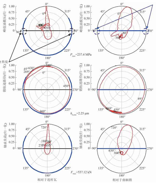
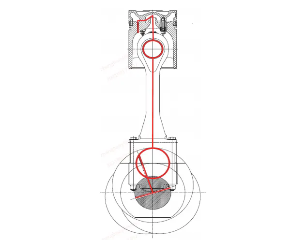
Fig. 6 is the axial trajectory of the connecting rod journal, and the red trajectory line is the axial trajectory of the connecting rod journal;
The blue line is the oil film coverage, in which the left column is the oil film range of the connecting rod pad, and the right column is the oil film range of the connecting rod journal, that is, the oil film range of the crank pin shown in the figure.
This type of diesel engine connecting rod bearing bears the maximum load near the top dead center of the connecting rod.
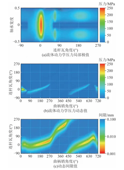
Fig. 7 is the conglomerate of oil film pressure distribution of connecting rod pads, and the area with the largest oil film pressure near the top dead center is also the area, which further illustrates that oil grooves and oil holes should not be arranged in this area, regardless of connecting rod pads or bearing housing holes.
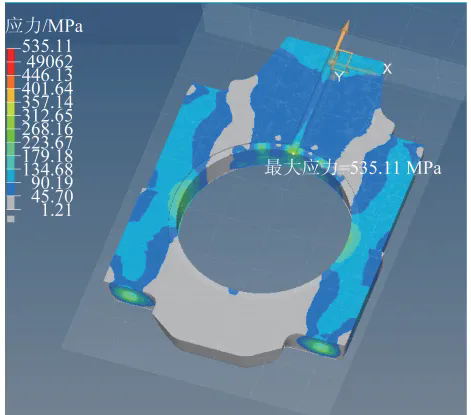
The linkage stress near the top dead center is simulated and calculated, as shown in Figure 8.
The large head hole of the connecting rod corresponding to the tile back on the connecting rod is arranged with an oil groove and an oil hole, and the maximum stress of the main bearing area corresponding to the position of the oil groove and the oil hole reaches 535. 11MPa, the connecting rod material is 42CrMoA, the allowable stress is 600MPa, but the bearing steel back material is 10# steel, the allowable stress is only 250MPa, the actual stress far exceeds the stress limit of the material, easy to cause bearing deformation, cracking.
This further proves that the unreasonable arrangement of oil grooves and oil holes in the main bearing area of the connecting rod body is the root cause of the failure.
(2). Bearing thickness
In large low-speed diesel engines, the ratio of bearing thickness t to bearing diameter D is generally more than 0.10, which makes the backing stiffness large and the housing hole accuracy is low, but the alloy layer is generally thicker, so that the alloy layer can be further scraped to achieve a uniform fit after assembly, but this may lead to a decrease in the bearing capacity of the alloy layer, which is not convenient for interchangeability.
At present, thin-walled bearings are generally used in medium and high-speed diesel engines, and the design reference value of t/d is 0.02~0.05, t is 1.5~7.0mm, and the thickness of the alloy layer is 0.2~0.7mm.
The t/D of the faulty diesel engine connecting rod bearing is 0.0173, which is lower than the lower limit of the thin-walled bearing, and the wall thickness of the bearing is thin.
As mentioned above, this type of diesel engine arranges oil grooves and oil holes in the maximum stress area of the bearing seat hole, which leads to a large deformation of the bearing after being subjected to bending stress, and the thin wall thickness of the bearing further aggravates the deformation of the bearing.
Under the action of the bearing load, the wall surface is depressed downward due to the loss of support from the back, and the wall at the edge of the depression area is convex upward, resulting in early wear of the alloy layer here.
The edge of the depression area is cracked due to stress concentration, and the depression area is no longer stressed and the crack is no longer expanded.
In the most severe cases, the back of the bearing in the depression area falls off, crushes the connecting rod bearing hole, and blocks the oil hole and oil passage, causing greater mechanical accidents [6].
Therefore, the wall thickness of the connecting rod tile does not meet the design requirements, and the thickness of the connecting rod tile is thin, which is an important reason for the rupture of the connecting rod tile.