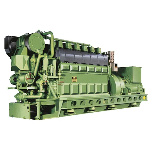
NAKAKITA pneumatic PID regulator (hereinafter referred to as the regulator) is widely used in ships, and is often used to control the water temperature of the main engine cylinder jacket, the temperature of the main engine lubricating oil, fuel viscosity and other parameters.
Whether the PID parameters are set correctly affects the stability of the whole system.
Once, when the main engine started and accelerated, the water temperature of the main engine jacket rose from 85 °C to 90 °C (the red pointer of the control unit was set at 85 °C), and the control unit of the regulator had no output signal until about 93 °C.
If the main engine accelerates too fast, resulting in the rapid rise of the water temperature of the cylinder jacket, it is also necessary to artificially adjust the set value, and increase the deviation between the set value and the measured value, so that the control unit can have output, and then the control unit can automatically adjust the output according to the deviation, so that the water temperature of the main engine cylinder liner is kept at the set value.

1. Fault analysis and treatment
According to the fault phenomenon, except for the acceleration of the main engine operation, the water temperature of the cylinder liner rises too fast, and the regulator can not be adjusted in time, the other times can be adjusted normally, and the sensitivity of the controller control unit can be judged to be insufficient, and when there is a deviation, the control unit can not output immediately, resulting in the adjustment is not timely enough.
Check the PID knob setting value on the control panel:
The ratio band is 125%, the Reset Time is 0.5 minutes, and the Rate Time is 0.15 minutes.
The proportional band plays a leading role in the adjustment effect, the larger the proportional band, the smaller its regulating effect, so the proportional band is set to 125%, and its role is also relatively small, which will lead to the adjustment is not timely enough, and the above fault phenomenon occurs.
The proportional band is set at 60% according to the adjustment method in the manual and the empirical setting when the control object is temperature.
Since the integral is only used to eliminate the static deviation, the effect does not need to be strong, and the Reset Time is set to 2 minutes.
Rate Time is set to 1 minute.
When the main engine starts to run and accelerates again, and the water temperature of the main engine cylinder liner has a tendency to rise, the control unit of the regulator immediately outputs to keep the water temperature of the cylinder liner stable at the set value.
When the main engine speed is running constantly, the water temperature of the main engine cylinder liner is also very stable, and there is no obvious fluctuation, indicating that the PID knob setting value of the control unit is correct.
By correctly setting the setting value of the PID knob of the regulator control unit, the failure of the water temperature regulator of the main engine cylinder liner was solved.
2.the composition of the regulator
- 2.1. The regulator is composed of four basic units:
Control unit, actuator, control object, measuring unit.
Together, these four units form a closed feedback control system (as shown in Figure 1).
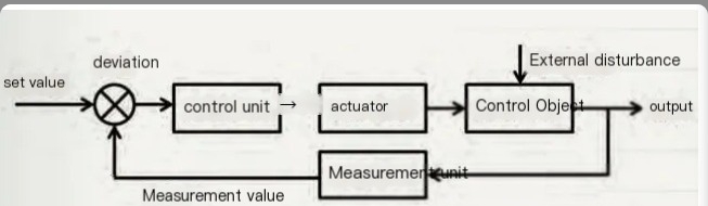
Fig.1 Diagram of the closed feedback control system of the regulator
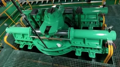
The physical diagram of the control unit and actuator of the regulator (as shown in Figure 2).
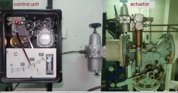
Fig.2 Physical diagram of the control unit and actuator
2.2 The working principle of the regulator:
When there is a deviation between the measured value of the measuring unit and the set value of the control unit, the control unit will output a signal to the actuator, and after the actuator acts, the control object is changed, so that the measured value is consistent with the set value.
2.3. In actual work, the probability of failure between the actuator and the measuring unit is very small, and the control object is fixed, so the maintenance of the regulator is mainly in the control unit.
3. The control unit of the regulator
3.1. The composition of the control unit (as shown in Figure 3):

It is composed of nozzle baffle, pneumatic power amplifier, proportional bellows, integral bellows, integral air chamber, differential bellows, differential gas chamber, various purpose levers and other components, and the structure is compact and complex.
On the left side of the control unit, there are two hands, one black and one red, the red pointer represents the set value and the black pointer represents the measured value.
There is a screw in the middle of the proportional band knob in the upper part of the control unit, which can be removed to clear the internal nozzle baffle.
A small button on the left side of the pneumatic power amplifier of the control unit is used to clean the throttle when pressed.
The dial in the lower right corner of the control unit has two hands, the right hand is the input pressure of the air source, and the pressure is adjusted through the pressure regulator to keep the pressure constant.
The pointer on the left is the output air pressure of the control unit, which is used as the input signal of the actuator.
There are three knobs in the upper part of the control unit to realize the PID function, the leftmost knob is the proportional band, the middle knob is Reset Time (i.e., I integration time), and the rightmost knob is Rate Time (i.e., D differential time).
2. Understand the function of the PID knob of the control unit
(1) Proportional band knob :
Its function is to make the output of the control unit change synchronously with the deviation, and the control of the system is more timely.
The disadvantage is that when the control object is disturbed, the measured value can only fluctuate up and down the set value in the end, and cannot return to the set value, and there is a static deviation.
When the inertia of the control object is large, it will lead to insufficient adjustment time.
The proportional band knob can be switched between positive and negative action.
The adjustment of the proportional band in the control unit plays a leading role.
The smaller the proportional band, the stronger its effect; The larger it is, the weaker it is.
(2)Reset Time knob:
The integration time is adjusted, and its effect is to eliminate static bias.
The regulation of the integral in the control unit plays an auxiliary role.
The addition of integrals to the proportional bands can overcome the disadvantage of static biases in the proportional bands.
The smaller the integration time, the stronger its effect; The larger it is, the weaker it is.
(3)Rate Time knob:
Adjust the differential time, the function of which is to control in advance.
The adjustment of the differential in the control unit also plays an auxiliary role.
The addition of integrals to the proportional band can overcome the disadvantage that the proportional band cannot be adjusted in time when adjusting the control object with large inertia.
The smaller the differential time, the weaker its effect; The bigger it is, the stronger it is.
3. Adjust the setting value of the PID knob of the control unit to the optimal method
(1) Reset Time is set to a maximum of 20 minutes, and Rate Time is set to a minimum of 0.05 minutes.
(2) Adjust the proportional band from 250% to 10% direction, and write down the size of the proportional band when the measured value begins to fluctuate, and the optimal proportional band is 2 ~ 4 times of the proportional band.
For example, when the proportion band is 25%, the measured value starts to fluctuate, and the optimal proportion band is 50%~100%.
(3) After the scale band is set, slowly adjust the Reset Time to a smaller level, and when the measured value starts to fluctuate, turn the Reset Time back a little bigger.
(4) The Rate Time is generally set to 1/4 to 1/2 of the Reset Time.
(5) Experience setting
For temperature and viscosity control:
The ratio band is 50%, the Reset Time is 1 minute, and the RateTime is 0.1 minutes.
For pressure control:
Proportional band 25%,
Reset Time 0.5 min,Rate Time 0.05 min。
4. Maintenance of the control unit
The internal structure of the control unit is compact and complex, with high reliability and simple maintenance.
(1) It should be noted that the control unit should not be vibrated and the internal connection mechanism and bellows should be damaged.
(2) Ensure that the air source of the control unit is dry, and regularly discharge the air through the residual valve at the lower part of the pressure reducing valve to ensure that the air source is free of oil and water.
(3) Regularly clean the hole through the nozzle baffle on the proportional belt.
(4) Press the small button on the pneumatic power amplifier regularly to clean the throttle hole.