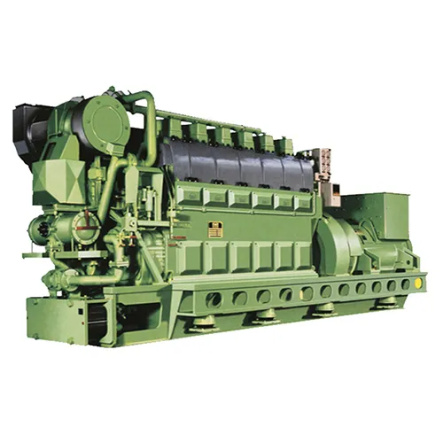
A ship has a total of 5 auxiliary engines, using 6L23/30H diesel engine produced by MAN B&W, with a rated speed of 750r/min.
When the speed exceeds 110r/min, the diesel engine starts with ignition.
One day, the dock was ready to sail, and the 4# auxiliary engine failed to start, and the specific phenomenon was as follows:
The 4# auxiliary engine is started next to the machine, the speed cannot reach 110 r/min, it cannot fire normally, and the diesel engine fails to start; Start again, the fault is still the same.
1. Troubleshooting
According to the reasons for the failure of the auxiliary engine to start the fire, the troubleshooting method is applied to conduct a comprehensive inspection of the auxiliary engine and its system, mainly in the following aspects.
(1) Check the fuel supply system, and find that the pressure and temperature are normal, there is no blockage, no leakage, and no obvious bubbles and impurities are found.
Therefore, the possibility of a failure of the fuel system is ruled out.
(2) Check the starting air system, and find that the air pressure is normal, the air source is sufficient, the starting motor is running normally, and the auxiliary engine can be driven to reach the ignition speed.
(3) Check the governor of the auxiliary machine, the stop lever in the governor or the top rod in the parking solenoid valve can move flexibly, and it is not stuck in the parking position.
Check the other parts in the governor, the operation is normal.
Eliminate the possibility of a faulty governor.
(4) Check the throttle control mechanism.
The rack of each cylinder fuel injection pump is flexible and has no stagnation.
Judging from the operation data and maintenance of the auxiliary engine before it is stopped, the fault that the auxiliary engine cannot start due to the large wear of the plunger parts, fuel leakage, and insufficient piston pump oil pressure is ruled out.
(5) Check the fuel injection timing of the auxiliary engine, and no phenomenon of too early or too late injection advance angle is found.
(6) Turning the car, check the intake and exhaust valves, and the intake and exhaust valves move up and down flexibly; The camshaft box was inspected, and no reason for the difficulty in starting the auxiliary engine was found.
(7) Check the overspeed protection device, the appearance is normal, and there is no alarm.
2. the root cause of the fault
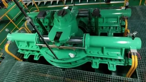
When inspecting the Lambda cylinder, the actuator of the overspeed protection device, it was found that the piston rod of the cylinder acted on the parking rocker arm, and the total rod of the throttle control mechanism was pushed to the zero position.
The initial fault point was the abnormal operation of the Lambda cylinder, an overspeed protection device.
Under normal circumstances, this cylinder only takes in air during emergency shutdown or overload, other times the cylinder is in a released state, and the cylinder piston rod is retracted under the action of the spring.
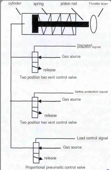
The working principle of the Lambda cylinder is shown in Figure 1.
3. Failure analysis
The Lambda cylinder takes in 3 situations with the piston rod extended, controlling the throttle.
(1) Load control.
According to the proportional relationship between the fuel rack scale and the booster air pressure, the throttle is controlled by the proportional air control valve to prevent too much fuel from being injected into the combustion chamber when the load of the diesel engine increases instantaneously, and to avoid the overheating load of the diesel engine.
(2) Emergency stop function.
In the event of mechanical overspeeding, through mechanical transmission, the two-position two-way air control valve is controlled, the Lambda cylinder is intake, and the piston rod is fully extended, forcing the throttle lever to the zero position and forcing the diesel engine to stop.
(3) Emergency stop function.
In the case of low pressure or high temperature water safety protection of lubricating oil, the safety system is excited, outputs a stop signal, controls the two-position two-way air control valve, the Lambda cylinder intakes, and the piston rod is fully extended, forcing the throttle lever to the zero position to force the diesel engine to stop.
Loosen the intake line at the top of the Lambda cylinder and find that strong compressed air has entered the cylinder.
When this air path is completely disconnected, the cylinder piston rod is free-resetting by the action of the spring.
Therefore, it is judged that the reasons for the difficulty in starting the auxiliary engine are:
The mechanical overspeed protection device of the auxiliary machine fails, the Lambda cylinder is intake, and the auxiliary machine cannot start normally.
4. overspeed protection device
The mechanical overspeed protection device of the auxiliary machine is shown in Figure 2.
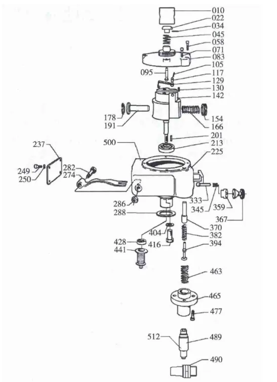
The overspeed protection device is installed at the cover of the lubricating oil pump, which is coaxial with the lubricating oil pump and driven by the crankshaft.
When the speed of the diesel engine exceeds the set value of 860r/min, the elastic flying block (191) moves outward and presses down the control shaft (274).
The control shaft (274) can be reset by the combined action of springs (382, 463).
The control shaft (274) acts on the mandrel (370,394), so that it moves down to open the air valve, and the air enters the Lambda cylinder controller to make the piston move downward, directly acts on the rack and pinion rod, and pushes the rack to the zero position.
The housing (225) is provided with an emergency operation hole, which can directly act on the mandrel (370) for emergency operation.
The manual release and reset of the overspeed protection device are realized by the button (022) and the button (367) respectively.
An inspection of the mechanical overspeed protection device revealed that the protective device was in the parked position and the manual reset failed, causing compressed air to act on the Lambda cylinder.
Therefore, the root cause of the failure lies in the mechanical overspeed protection device.
Dismantling mechanical overspeed protection devices, replacement of accessories, troubleshooting.
5. Expand inspections
The remaining 4 auxiliary overspeed protection devices were inspected, and it was found that except for the 1# auxiliary mechanical overspeed protection device that could be used normally, the rest had different degrees of failure, see Table 1.
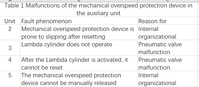
Due to the problems of many auxiliary machines, after contacting the manufacturer, the 2# and 5# auxiliary mechanical overspeed protection device assembly and travel switch were replaced, the pneumatic valve switch of the 3# auxiliary protection device was cleaned and dredged, and the pneumatic valve switch of the 4# auxiliary protection device was replaced.
These measures enable the mechanical overspeed protection device to be used normally, and the 5 auxiliary units can operate normally.
In order to find out the root cause of the failure of the 2# and 5# auxiliary mechanical overspeed protection device, the 2# and 5# auxiliary mechanical overspeed protection device was dismantled and inspected, and it was found that there were impurities and oil stains in the emergency operation hole of the device, resulting in the stagnation of the mandrel (370) and the failure of the control shaft (274) to be completely reset.
In order to prevent the recurrence of similar situations, install 1 plug to close the emergency operation hole to prevent dirt from entering the emergency operation hole and affect the flexible movement of the mechanism.
At the same time, in the usual maintenance management, the following two aspects need to be noted:
(1) Regularly inspect the overspeed protection device and carry out a manual release test to ensure that the device works normally.
(2) The air path is often discharged, and the air filter is regularly maintained and cleaned.
5. Concluding remarks
The timely detection and treatment of this fault ensures the normal use of the emergency protection device of the ship’s auxiliary engine.
At the same time, it is necessary to sound the alarm bell for equipment management personnel, to have a clear understanding of the principle of equipment construction, and to regularly maintain and inspect the equipment safety protection device.