Combined with actual cases, this article analyzes the causes of the failure of a certain wheel gearbox and explores the ways and methods to solve the problem.
Through the solution of faults, the safe operation of the ship is ensured.
1. Ship-related information
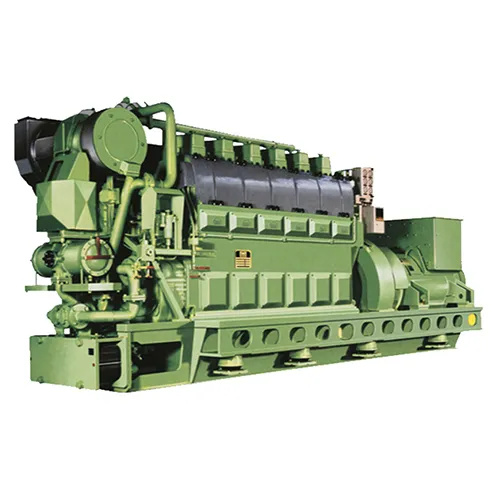
A ship is a three-purpose tugboat with the ability to tow, supply and assist anchor lifting operations, equipped with double main engine, double propeller and double rudder, each independent gearbox, main engine MAN 9L32/44CR, using common rail EFI system, rated power 5040KW×2.
Gearbox model LAF 6755HR K41A, with generator on the output shaft of the PTO output shaft through gear meshing, reduction ratio 4.217:1, hydraulic meshing clutch drives the stern propeller, simultaneous linkage Dynamic CPP control system.
2.The failure phenomenon of gearbox
The gearbox of the right main engine of a certain wheel often fails in operation, and the phenomenon is as follows:
(1) The lubrication pressure of the gearbox of the right machine is lower than that of the left machine when the gearbox is running;
(2) The clutch often fails to fit when preparing the car;
(3) When the clutch is closed and accelerates to 500r/min, it often disengages malfunctionally;
(4) In the process of completing the car after the main engine has been running for a long time, the clutch is easy to fail when the speed is reduced to 500r/min.
3.The gearbox working procedure
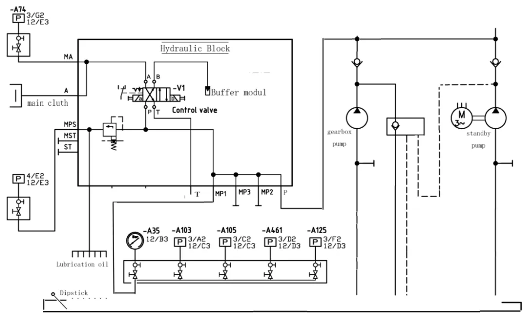
According to the control system diagram (see Figure 1), the working procedure of the gearbox is:
The operation starts the main engine, the main engine idles at 450r/min and runs normally (due to the one-way valve between the pre-lubricating oil pump and the belt pump, the belt pump is in the unloading and backflow working state at this time), the system oil passes through the relief valve to each fulcrum to lubricate each part, and the other way passes through the two-position four-way valve P port to B port to the accumulator (buffer modul) pressure storage.
Operate the clutch of the main engine, the right side of the two-position four-way valve is turned on, and the working oil is passed through the two-position four-way valve P port to A port to the main clutch.
When the clutch is closed, when the main engine accelerates to 500 r/min after closing the clutch, the pre-lubricating oil pump will automatically stop, the machine belt pump will be put into work, and the speed of the main engine will be increased to 750r/min and then the fixed speed will run.
4.Gearbox troubleshooting and analysis
In view of the failure phenomenon of the equipment, it is inspected from the following aspects:
(1). Check the electronic control signal of the solenoid valve group
Monitoring the electronic control signal of the solenoid valve group (see Figure 1 solenoid valve a, b), the measurement obtains:
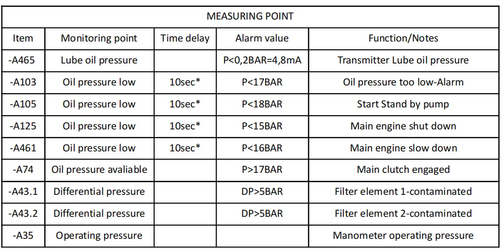
The electronic control signals sent by the control system are normal when closing and disengaging the coupling, and the feedback signals at the monitoring of -A465, -A103, -A74 and so on (see Figure 2) are also normal.
(2). Check the relief valve at the valve group
Measure the working pressure (-A35operating pressure) before the left and right gearbox relief valves are 26bar (the minimum clutch working pressure is 17bar), but the lubrication pressure behind the valve (-A465lube oil pressure) is significantly different (left 0.7 bar / right 1.7 bar), adjust the left and right relief valve pressure regulators, and the lubrication pressure remains basically unchanged when the working pressure rises and falls significantly.
(3). Check and analyze the pressure of lubricating oil
Lubrication pressure (-A465) after testing the relief valve:
Lubrication pressure pipe to the lubrication point a total of 10 branches, because there is no detailed description of each lubrication point in the construction drawings, can only open the corresponding door of the left and right gearbox together to open the lubricating oil pump, and the corresponding lubricating oil flow of each lubrication point is compared, and at the same time compare the diameter of the disassembled left and right branch pipes one by one.
After comparison, it was found that:
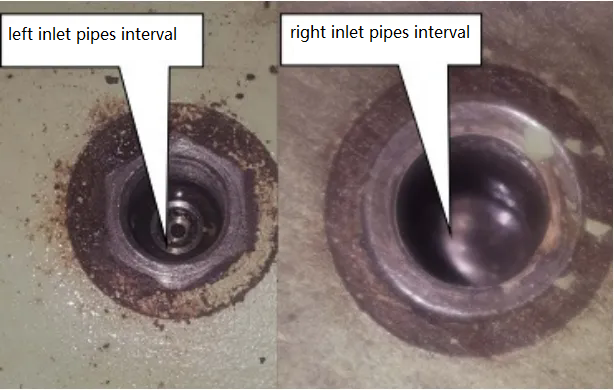
The oil flow rate at the first branch of the lubrication pipe system of the right machine is obviously greater than that of the left machine, and the disassembly pipeline finds that there is a bolt with an outer diameter of 10 mm and a built-in 3 mm damping hole at the left pipe inlet, but the bolt is missing on the right side (see Figure 3), which is basically the same as other inlet pipes.
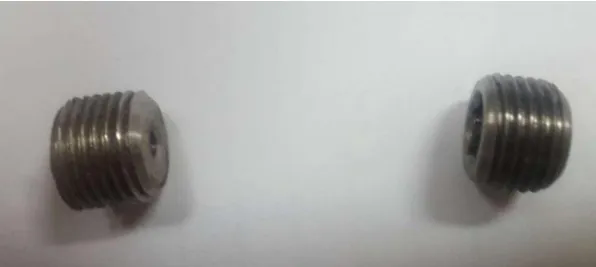
After the damping bolt (see Fig. 4) is installed on the right machine, the test lubrication pressure rises from 0.7 bar to 1.3 bar, and remains unchanged, and the original fault (2), (3), and (4) still exists in the closing clutch after the test.
By observing the instantaneous pressure change of the closing clutch, the following rules exist:
When the clutch of the left machine is closed, the working pressure of the lubricating oil is instantly reduced from 26bar to 8bar, but it also instantly returns to the normal working pressure, the pre-lubricating oil pump stops when the main engine accelerates to 500r/min, and the pressure drops to 18bar when the machine pump is put into work and instantly returns to the normal pressure;
When the clutch is closed, the working pressure drops to about 7bar, and sometimes it takes a long time to return to the normal pressure (at this time, it is the time when the clutch cannot be closed), when the clutch is successfully closed, the main engine accelerates to 500r/min pre-lubricating oil pump, and the working pressure drops to about 17bar when the pump is switched, and sometimes the holding time is longer (at this time, it is also when the clutch fault is disconnected);
After adjusting the relief valve to raise the working pressure to 28 bar, observe the closing and clutching situation:
The fault (2) phenomenon still exists in the early stage of the clutch (when the main engine speed is 450r/min), but when the main engine accelerates/decelerates to 500r/min and the pre-lubrication pump stops/starts switching, the working pressure drops to 18bar and quickly returns to the normal working pressure, and the initial failure (3) (4) phenomenon does not occur again after many tests.
Combined with the system diagram, the above analysis obtains that:
This series of faults can basically rule out electrical causes, and there is no direct correlation with the lubrication pressure behind the relief valve.
According to the working principle of the system diagram, it can be seen that:
Before closing the clutch, the working lubricating oil is carried on to the BUFFER MODUL after being conducted through the two-way four-way valve P-B, and the other way flows through the relief valve to the lubrication points, and the two-way valve core moves right to the P-A to turn on the clutch when closing the clutch, and the B-T conduction is discharged into the oil pan through the T port, and the specifications and models of the left and right gearboxes, belt pumps, pre-lubricating oil pumps and auxiliary pipe fittings are the same, but the above fault (2) phenomenon occurs when the right machine is closed, and the valve core of the two-way valve of the right machine is preliminarily suspected to be partially jammed and leaked. As a result, the P end and the T end are connected and relieved during the closing and clutching, so that the working pressure is reduced from 26 bar to 7 bar and cannot be restored to the normal pressure, resulting in the failure of the closing and clutching.
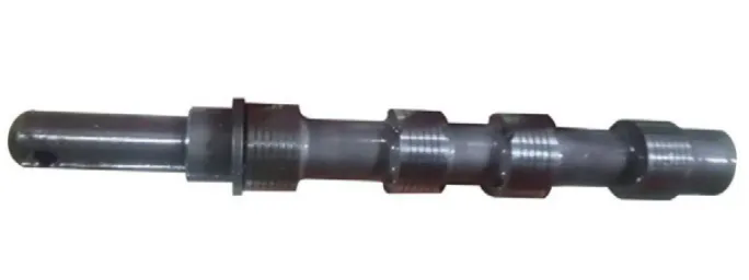
According to the above analysis, the two-position four-way valve of the right machine was disassembled, and the valve core was taken out (see Figure 5), and it was found that the valve core was not active in the valve cavity and there was a jamming phenomenon.
The two-position four-way valve was replaced with the left machine, and the fault (2) phenomenon of the right machine was eliminated after assembly, but the left machine had the same fault (2) phenomenon as the right machine.
5. Analyze the results and solutions
The fault phenomenon (1) is related to the lack of damping bolt, because the place is the first pipe after the relief valve, and the oil hole is too large to cause the back pressure of the relief valve to be insufficient, resulting in the lubrication pressure is obviously lower than that of the left car, and it is easy to lead to poor lubrication at the subsequent fulcrum, but after the installation of the missing damping bolt, there is still a phenomenon that the lubrication pressure is lower than that of the left car, which shows that the lubrication pressure pipe system of the right machine still has an undiscovered larger inlet clearance than the left machine.
The fault phenomenon (2) is caused by the jamming of the valve core of the two-position four-way valve, and the replacement valve group completely solves the fault.
Dealing with faults (3) and (4) is to increase the working oil pressure (26bar→28bar) in front of the valve by adjusting the relief valve, increase the buffering effect of the accumulator and hedge the pressure drop caused by the large gap between the inlet pipe system, so that the pressure drop of the working pressure when the main engine accelerates or decelerates the lubricating oil pump when switching (28bar→18bar), and avoids the possibility of faulty disengagement;
When the speed of the main engine is reduced to 500r/min after long-term operation, the phenomenon of disengagement occurs at the switching node of the standby pump, which is due to the high oil temperature and low viscosity caused by the long-term operation of the machine, which is easy to reduce the pressure to below 17bar during switching, resulting in low pressure disengagement, and the cooling effect is increased by increasing the lubricating oil pressure and appropriately adjusting the cooling water temperature to ensure that the failure (3) and (4) do not occur again.