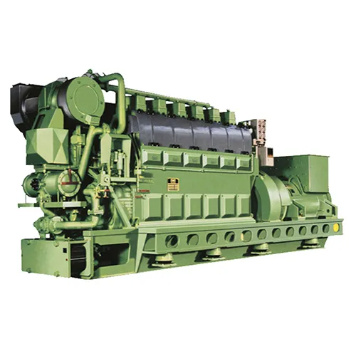
This article introduces the functions, working principles, and piping layouts of the charge air bypass valve and the exhaust gas bypass valve in the exhaust gas turbocharging system.
1. Pressurized air bypass valve
The booster air bypass valve is installed on the communication pipe between the scavenger box and the exhaust gas inlet of the supercharger, so that the supercharger has sufficient surge margin when the main engine is under low load.
When the main engine runs at low load, the air consumption of the main engine is small and the booster pressure increases, which is easy to cause high back pressure of the compressor and surge of the supercharger.
Therefore, open the booster air bypass valve to reduce the back pressure of the compressor, increase the kinetic energy of the rotor, and increase the surge margin.
The bypass system is controlled by the speed and load of the main engine.
The charge air bypass valve is controlled by an electro-pneumatic valve with control signals from a series connection speed relay and a charge air pressure sensor.
When the speed of the main engine is less than 425r/min and the pressure of the charge air is greater than 0.35bar, the charge air bypass valve is opened, and part of the charge air enters the exhaust pipe before the booster from the compressor, increasing the speed of the booster.
2. Wastegate valve
The wastegate valve is installed on the connecting pipe at the exhaust gas inlet end of the supercharger to maintain the optimal operating condition of the main engine under high load.
The main engine is in the best working condition at 85% load, that is, high boost pressure, low exhaust temperature, and low fuel consumption rate;
When the load exceeds 85%, the boost pressure and cylinder combustion pressure are too high, and the wastegate valve allows part of the exhaust gas to bypass the supercharger and reduce the exhaust gas flow into the turbine end.
The wastegate is controlled by 1 electro-pneumatic valve, whose control signal comes from the charge air pressure sensor.
When the main engine charge air pressure is greater than 3 bar, the wastegate valve is activated, and a part of the exhaust gas is directly discharged from the smoke exhaust main pipe without passing through the turbine blades, so that the boost pressure and cylinder combustion are controlled at the optimal level.
3. The pipeline layout of the booster air bypass valve and the waste gas bypass valve
Exhaust gas pressurization system pipeline diagram 1.

The charge air bypass valve 5 is located at line A connected to the scavenger box, and when 5 is opened, the charge air from the scavenger box 7 reaches the exhaust gas main through pipeline A and line B, increasing the rotational speed of the exhaust gas turbine.
The wastegate valve 4 is located at the place where the turbocharger turbine leads to the exhaust line C, and when the booster pressure is too high, the 4 action causes part of the exhaust gas to be discharged directly through pipeline B and pipeline C without passing through the exhaust gas turbine.


