The disassembly and assembly of the high-pressure oil pump with VIT structure, several steps on the manual are very complicated, and the article summarizes and refines the steps in the manual with the actual operation, so that it can explain the problem concisely and concisely.
The fault phenomenon
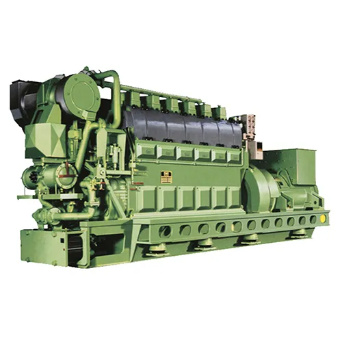
The main engine of the JYH wheel is the MAN B&W 5L60MC model, with a variable fuel injection timing adjustment mechanism (i.e. VIT), and its camshaft system is a separate lubrication system, and the system circulating oil volume is about 800L.
For a long time, the oil volume of the camshaft circulating oil tank has a tendency to increase, and it is accompanied by the phenomenon of a gradual decrease in lubricating oil pressure.
It was preliminarily judged to be caused by the leakage of external medium into the camshaft lubrication system.
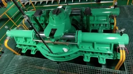
In the camshaft box, there are two cams in each cylinder position and their acting objects:
Exhaust valve and high-pressure oil pump cam and their respective top wheel guide bushing mechanism.
The whole system is only in contact with the outside world here, and because the valve opening oil and the camshaft oil on the upper part of the exhaust valve top wheel guide sleeve mechanism are the same medium, even if it leaks here, it is not easy to cause the system pressure to decrease. Therefore, the author judges that the internal fuel of the high-pressure oil pump leaks into the camshaft lubrication system. So start the main engine fuel pump, open the camshaft inspection holes of all 5 cylinders, and find that the fuel leaked at the top wheel of the high-pressure oil pump of the 3 #cylinder is almost flowing, followed by the 4 #cylinder.
Disassembly and assembly steps
Before disassembling, read the main engine maintenance and spare parts manual in detail.
There are two tie rods at the base of the high-pressure oil pump of the main engine of the wheel, and the lower part is the throttle rod. The rack of this tie rod drives the plunger of the high-pressure oil pump to rotate circumferentially, thereby changing the end point of fuel injection, so as to achieve the purpose of changing the fuel injection amount.
The upper part is the VIT tie rod, the rack of this tie rod causes the high pressure oil pump sleeve to move axially by driving the timing block to rotate, so as to change the fuel injection start point and achieve the purpose of changing the fuel injection advance angle.
Check the maintenance manual of the main engine to find that the high-pressure oil pump requires 14 steps from disassembly to assembly.
The replacement of the seal on the plunger and sleeve involves 13 steps.
The author summarizes two key steps for disassembly and assembly, and describes three points for attention in order to achieve the purpose of succinctly explaining the problem.
Let’s start with the 3# cylinder with serious leakage.
First, turn the cylinder fuel cam to the roller at the top dead center, that is, let the roller fall to the base circle of the cam, remember: Do not recoil during the disassembly process.
Turn off the relevant fuel line valves, and remove the upper end cover of the high-pressure oil pipe and oil pump.
At this time, there may be residual oil pressure at the oil outlet of the oil pump, and it is necessary to pay attention to the measures of slowly loosening the oil pipe and unloading the oil when disassembling to prevent the fuel from splashing out and injuring people.
2 key steps to remove the plunger sleeve:
1) Measure 2 pieces of data.
Loosen the connecting elbow of the VIT rod and the throttle lever, pull out the VIT and the throttle lever until they cannot be pulled, and measure the distance from the top of the plunger to the top of the sleeve with a vernier caliper;
Measure the distance from the top of the sleeve to the upper end of the pump body.
Record these two data as the basis for the installation and resumption;
2) Pull out 2 tie rods.
Loosen the locking device of the VIT lever and throttle lever on the pump body.
The VIT locking device is only a hexagon nut;
The outer end of the locking device of the throttle lever is a gland with 6 small bolts on this gland, none of which need to be removed, and the locking unit can be screwed out directly.
Pull out 2 levers until you can’t pull hard.
The throttle lever is easy to pull out, the VIT rod is more difficult to pull out, if it is not easy to do it by hand, it can be completed with a special pull-out tool.
Remove the circumferential positioning bolt of the sleeve on the pump body, and the plunger sleeve can be lifted out together with a special tool.
Note that in order to lift the two together, the two bolts on the upper part of the tool should be screwed into the threaded hole on the sleeve, and the thread at the bottom of the center long rod should also be screwed into the threaded hole at the top of the plunger, so that the two can be lifted out together;
3) After the plunger sleeve is separated, replace all seals (including the end cap of the pump body) as much as possible.
The replacement of other sealing orders is not described here, except for 520 SEALING BUSH, COMPL. The following 3 points should be paid attention to when replacing the sealing order:
a.Pay attention to the arrow mark on the 520 SEALING BUSH, COMPL. housing. The direction pointed by the arrow is the installation direction.
b. Pay attention to the installation direction of the 593 SCRAPER RING.
A total of two sets of 593 should be installed upwards on the cutting edge, relying on the upward installation of the cutting edge, in order to play the role of scraping oil upwards.
When installing the 593, do not place it “back-to-back” or “face-to-face” as imagined;
c. Note that the upper and lower glands of the 593 should not be mixed.
The name of the two gland is “BACK-UP RING”, which means that it is not only the gland that is used.
The inner diameter of the upper and lower gland is different, the upper part is numbered 568 and the inner diameter is larger, and the lower part is numbered 615 and has a smaller inner diameter.
Reflected in the appearance is that the lips of the seal are pressed tightly, one is thinner and the other is thicker.
The purpose of this design is to allow a small amount of fuel to leak into the lower part of the upper seal to lubricate the lower seal.
Careful study of the structural diagram shows that when all the sealing orders of the plunger sleeve are replaced, whether the internal leakage or external leakage of the high-pressure oil pump can be effectively prevented.
4) The process of assembling a high-pressure oil pump can also be summarized into 2 key steps:
a. Pull the 2 levers to inspect.
Install the plunger and sleeve into the pump casing together as you would when dismantling, and the circumferential positioning groove of the sleeve and the lower end of the plunger should be aligned with their respective positions during disassembly as much as possible.
Since the sealing order on the outside of the sleeve has been replaced, it will be a little difficult to install, the outside of the sleeve can be coated with lubricating oil to reduce the friction effect, you can use a hammer to hit the top of the disassembly tool to make it in place, pay attention not to directly knock on the top of the sleeve.
When you feel the “hard bump” metal impact sound, remove the disassembly tool and install the circumferential positioning bolt of the compound sleeve.
Pull the VIT rod to observe whether the sleeve moves up and down with the reciprocating pull of the VIT rod, if so, it can basically be determined that the sleeve is in place;
Pull the throttle lever to observe whether the plunger rotates circumferentially with the reciprocating pull of the throttle lever, if so, it can basically be judged that the plunger is in place;
b. Compare 2 data to support this.
At this point, push the VIT and throttle lever in, reinstall their locking devices, and pull out the 2 levers again until they can’t be pulled (because this is the high-pressure oil pump state for the first measurement).
The height data from the top of the plunger to the top of the sleeve and the top of the sleeve to the upper end of the pump body are measured respectively, and compared with the measured data when the initial disassembly is made, if it is consistent, it can be judged that the installation is in place;
5) There is also a way to judge whether the plunger sleeve is correct can be used as the “ultimate basis”.
At this time, the upper end cover of the high-pressure oil pump is reassembled, pressed diagonally with 2 fastening bolts, and then the bolt is removed, and the upper end cover of the oil pump is carefully observed whether it is lifted.
After installing the high-pressure oil pipe, tie rod connecting elbow and other accessories, turn on the fuel pump, and observe at the camshaft inspection hole, and there is no fuel leakage.
Subsequently, we carried out the dismantling and repair of the 4# cylinder high-pressure oil pump, which was implemented one by one according to the above steps, and the installation was intact.