An inductive sensor is a non-electric measurement device that uses the change of the self-inductance or mutual inductance coefficient of the coil to achieve non-electric quantity. Inductive sensors can be used to measure parameters such as displacement, pressure, vibration, strain, and flow. It has a series of advantages such as simple structure, high sensitivity, large output power, small output impedance, strong anti-interference ability and high measurement accuracy, so it has been widely used.
The inductive sensor uses the principle of electromagnetic induction to convert the measured non-electric power such as displacement, pressure, flow, vibration, etc. into the change of coil self-inductance L or mutual inductance M, and then converts it into the output of voltage or current change by the measurement circuit.
Let’s start by reviewing what self-inductance and mutual inductance are.
Self-inductance phenomenon: When the current in a coil changes, the changed magnetic field it generates not only excites the induced electromotive force in the adjacent circuit, but also excites the induced electromotive force itself, which is called the self-inductance phenomenon.
Mutual inductance: When the current changes in one coil, the phenomenon of inducing electromotive force in the other coil is called mutual inductance. The electromotive force generated in the phenomenon of mutual inductance is called mutual inductance electromotive force.
There are many types of inductive sensors, and the following three are common.
- self-sensing sensors;
- mutual inductance sensors;
- eddy-current sensors;
The commonly used inductive touch switch in automobiles is a kind of eddy current sensor, and before introducing the inductive touch switch, we will first introduce what the eddy current phenomenon is.
- Eddy current phenomenon:
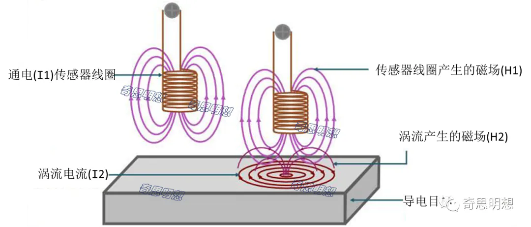
When the conductive target approaches the sensor coil with current I1, the conductive target surface is affected by the magnetic field H1 generated by the sensor coil, and the conductive target will form an eddy current current I2. The magnetic field H2 of these eddy currents hinders the current flow of the inductor coil, thereby reducing the inductance L of the system and thus increasing the resonant frequency f.
The formula for calculating the resonant frequency is: f=1/(2π√LC); f: natural frequency; L: Inductance; C: Capacitance;
2. Working principle of inductive touch switch:
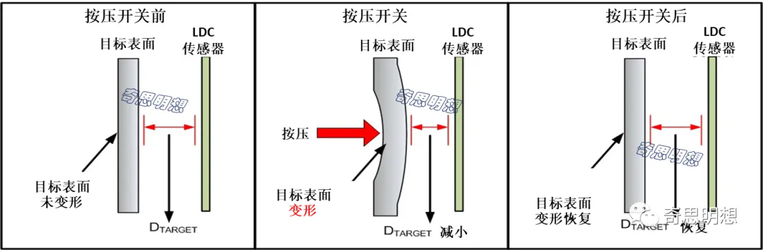
Inductive tactile switches can be easily implemented with three main components: the inductive sensor, the target surface, and the inductance-to-digital converter (LDC). Sensors can often be implemented with coils based on PCBs or flex circuits. The target surface should be a flexible, conductive material, such as a thin metal thick enough to support eddy currents for the skin effect. When a force is applied to the target surface, the material is slightly deflected, resulting in a shorter distance between the inductive sensor and the target surface (DTARGET). Deflection of the conductor results in a decrease in the sensor inductance L(d), which in turn leads to an increase in the sensor resonant frequency, which is detected by the LDC. In the target deflection example below, if the target material is 430 stainless steel with a thickness of 1 mm, the deflection of the button with a diameter of 20 mm will be about 0.1 μm. When the force is removed, the button surface returns to its original shape.
3. Factors influencing sensitivity:
3.1 Target Materials:
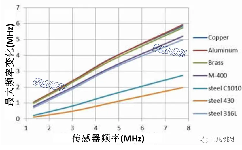
Materials with higher conductivity (σ) are more suitable for inductive sensing applications. The magnitude of the eddy currents generated on the target surface is directly related to the electrical conductivity (σ) of the target material. Materials with higher conductivity, such as copper, aluminum, or silver, are preferred targets for inductive touch buttons. A thin layer of conductive material can be added to a non-conductive material, such as plastic, to create an effective target surface for button applications.
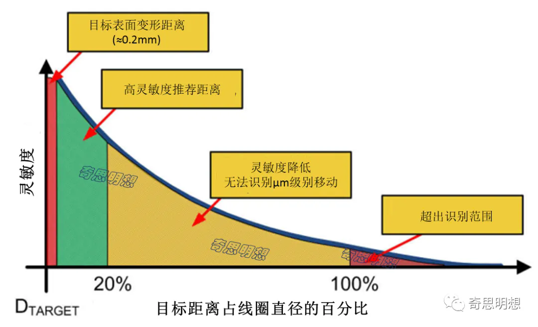
3.2 DTARGET and sensor size:
As mentioned earlier, inductive inductive switches rely on the interaction with the electromagnetic field generated by the inductive sensor. The electromagnetic field lines are proportional to the diameter of the sensor, and the eddy currents they generate on the target surface decrease as the DTARGET increases. The dependence of the switching sensitivity on the target distance is shown below, as it is related to the sensor diameter. AS SHOWN IN THE FIGURE, THE SWITCHING SENSITIVITY IS BEST WHEN THE DTARGET IS WITHIN 20% OF THE SENSOR COIL DIAMETER.
Top Recommended Inductive Sensors For ME-C Series