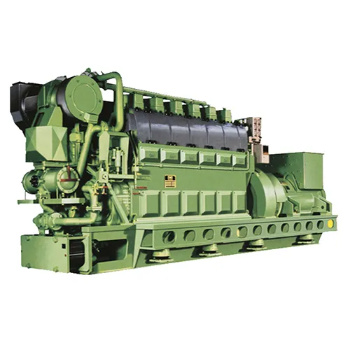
1. The working principle and composition of the speed regulation system(electronic governor)
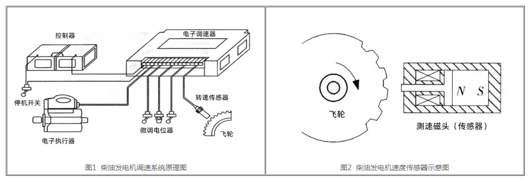
When the flywheel of the diesel generator rotates, the tachymeter head installed on the flywheel housing generates a pulse voltage signal, the voltage value exceeds 1.5VAC, and this voltage value is transmitted to the electronic speed control board, if the speed is lower than the preset value of the electronic speed control board, the pressure output of the electronic speed control board to the electronic actuator rises, then the oil supply of the PT oil pump increases accordingly, so that the speed of the diesel generator reaches the preset value of the electronic speed control board. The speed regulation system of diesel generator set comprises an electronic speed control board, a speed measuring head, and an electronic actuator, and the composition schematic diagram is shown in Figure 1.
1.1 Tachymeter head
The tachymeter head, also known as a speed sensor, works as shown in Figure 2. The coil can be tested by the multimeter ohm file on the two terminals of the coil, the resistance value is generally between 100-300 ohms, the terminal block is insulated from the housing of the tachymeter head, and the generator set is working normally, the AC voltage gear is used for detection, and there should be a voltage output of more than 1.5V.
When installing the tachometer head, turn any tooth of the flywheel to the center of the circle of the tachymeter head mounting hole, and then gently screw the tachymeter head in, after the tachometer head touches the teeth, then rotate back 1/3-3/4 times counterclockwise, and finally tighten the tachymeter head with a nut.
1.2 Electronic actuators
Diesel generator external electronic actuator. The coil of the electronic actuator can be detected by the multimeter ohm file on the two terminals of the coil, the resistance value is generally between 7-8 ohms, when the power generation is to run without load, the voltage value of the electronic speed control board to the electronic actuator is generally between 6-8VDC, and the voltage value will increase with the increase of load, and when fully loaded, it is generally between 12-13VDC. When the generator set is no-load, if the voltage value is lower than 5VDC, it means that the electronic actuator is overworn, and the electronic actuator needs to be replaced; When the generator set is under load, if the voltage value is higher than 15VDC, it indicates that the PT oil pump is undersupplied.
Electronic actuators are divided into two types: normally closed and normally open. Generally, normally closed actuators are used (that is, the oil hole of the actuator is in a closed state under the condition that electricity cannot be elected), and normally closed actuators must be equipped with normally closed electronic speed control plates.
2. the installation of electronic governors
The speed controller is usually installed in the control cabinet or directly fixed to the diesel generator set, and the external installation dimensions are shown in Figure 2. The speed controller is protected from moisture, but water, fog or condensation must still be protected from contact with the controller. And the installation should be kept away from high temperature or thermal radiation to prevent the controller from being damaged by high temperature.
2.1 Governor installation steps
(1) First of all, take out the governor and carry out the necessary inspections to confirm whether the quality of the governor and other components meets the installation standards.
(2) Select the installation position of the governor and make a pre-hole on the side of the installation position. The size and location of the mounting holes should match the size and model of the governor.
(3) Install the governor into the pre-opened mounting hole, and pay attention to maintaining the level and verticality between the governor and the bracket during installation. At the same time, it is necessary to ensure that the coaxiality between the output shaft and the load shaft of the governor meets the requirements during installation.
(4) After the installation of the governor is completed, it is also necessary to make electrical connections and wiring of the control loop. These tasks need to be carried out according to the specific governor model and control system.
2.2 Wiring of the governor
(1) The external wiring method of the electronic speed control system, in which the actuator is connected to 1 and 2 terminals, and the battery pack is connected to 5 or 6 terminals, and these two sets of wires require a cross-section of 1.3 mm2 or thicker wires. The longer the wire, the thicker the wire diameter is required to reduce the pressure drop.
(2) The positive pole of the battery pack (i.e., terminal 6) should be connected in series with a 15A fuse.
(3) The speed sensor is connected to 3 and 4 ends, and the sensor wire requires the use of shielded wire, and its shielding part should only be connected with terminal 4 and completely insulated from other parts, otherwise the occasional external signal may enter through the speed signal, which causes the diesel generator set to stop or work abnormally. The installation of the speed sensor should be 1/2-3/4 turn (about 0.45mm) after touching the top of the gear tooth, which is an ideal clearance.
3. Adjustment of electronic governor
3.1 Adjust the equipment before starting
Observe the potentiometer that adjusts the gain and stability, which is generally set at 12 o’clock (i.e., in the middle) at the factory; The idle potentiometer is used to set the speed of the diesel generator set when it starts; When the external speed switch is disconnected, the diesel generator set is converted from idle speed to rated speed; The rated speed potentiometer is used to adjust the rated speed of the diesel generator set.
The controller has been set up at the factory, so there is generally no need to adjust the controller before starting the diesel engine, and the user only needs to make fine adjustments after starting the diesel generator set.
3.2 Adjustment of the controller after starting
(1) When starting, the actuator should supply the maximum amount of oil until the diesel generator set starts, and the controller should be controlled in the idle position. If the diesel genset is unstable after starting, adjust the gain and stability potentiometer counterclockwise until the diesel genset is stable.
(2) The external high/low speed transfer switch is disconnected, and the diesel generator set enters the rated speed. Adjust the rated speed potentiometer or external trimmer potentiometer to precisely adjust the rated speed, and increase the clockwise rotation frequency at the rated speed setting point.
(3) After starting, the diesel generator set should be adjusted as follows when it is not loaded:
①Rotate the gain potentiometer clockwise until it is unstable, then fine-tune it counterclockwise until the system is stable, and then adjust a portion further counterclockwise to ensure stability.
② Rotate the stability potentiometer clockwise until there is an unstable state, then adjust it counterclockwise to stability, and further fine-tune a part of it counterclockwise to ensure the stable rotation of the diesel generator set.
③ After the gain and stability are adjusted, the rated speed is adjusted by the trimmer potentiometer to meet the design requirements of the unit.
④ If the diesel generator set needs to introduce idle operation, the high/low speed switch is closed, and then the idle potentiometer is adjusted to the required speed, and the frequency is increased clockwise when adjusting (usually 50% of the rated speed).
3.3 Adjustment of steady-state rate modulation
(1) The adjustment of steady-state rate regulation is suitable for use when multiple units are running in parallel.
(2) The terminals 10 and 11 are short-circuited to make the droop characteristics of the diesel generator set soft, and the speed of the diesel generator set will decrease with the increase of the load of the diesel generator set, and the clockwise adjustment increases the steady-state regulation rate, and vice versa.
(3) If the steady-state regulation needs to be in a larger range, short the 7 and 8 terminals, and the steady-state regulation rate can reach 10%.
(4) After the adjustment is completed, the speed of the diesel generator set will change slightly, and then the speed setting will be re-set.
4. Auxiliary input
(1) terminal 13 is used as an auxiliary input signal, and its signal is imported from load distribution unit, automatic synchronization device and some other control system.
(2) When the auxiliary input signal is introduced, the speed will decrease, and the speed needs to be set again; When an auxiliary input signal is not introduced, a trimmer potentiometer can be connected between 7 and 9 and adjusted manually.
5. Auxiliary output
Terminal 14 can supply 10V, 20mA power supply externally for external system power use, but if a short circuit occurs in use, the controller will be damaged.
6. Overspeed protection
(1) When the diesel generator set is running at 105% of the rated speed, press and hold the “test” button, rotate the “overspeed” potentiometer counterclockwise until the overspeed light is lit, the relay action, and turn off the diesel generator set.
(2) Release the “test” button, after the diesel generator set stops, press the “reset” button or disconnect the power supply once, and then start the diesel generator set again.
(3) The overspeed setting value is generally about 115% of the rated speed, and the overspeed value has been set at the factory, and the user generally does not need to adjust it.
Summary:
In short, the principle of automatic speed regulation of diesel generator set is to control the fuel supply of the engine to achieve the stability of the output voltage and frequency of the generator set. Governors, actuators, sensors and controllers form the key components of the automatic speed control system, which work together to ensure that the generator set can maintain a stable output during operation. This system not only improves the stability and reliability of the generator set, but also improves its operating efficiency and service life.
Spare Parts Recommendation for Electric Governor (applicable to WOODWARD)
Sino-ocean Marine’s inventory provides spare parts for electric governor(applicable to WOODWARD),such as Digital Load Sharing &Speed Control,Electric Governor ,Large Engine Control Module and Programmer Hand Held,as well as brand new imported parts from the original factory. We welcome inquiries from customers and friends.