Guide: The article judges and analyzes the faults of the monitoring system of the MAN B&W L27/38 main engine and proposes solutions to the faults.
1. Overview
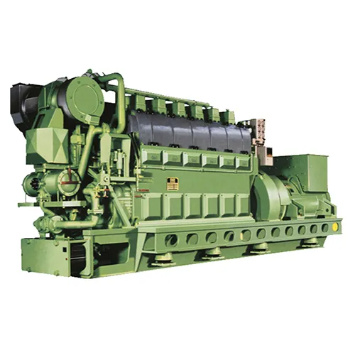
The main features of a ship are the L27/38 main engine produced by MAN B&W, and its main features are: the diesel engine adopts the principle of fully electronic and redundant instrument design, which provides the operator with rich monitoring functions and a good observation interface.
The OP-E operating panel next to the diesel engine is located near the governor, so that the operator can easily monitor and control the diesel engine from only one position.
The diesel engine monitoring system ACM-E is serial connected to the ship’s alarm system and transmits and receives the measured values of all sensors.
The tasks it performs are:
Collect data and display it on the operation panel OP-E next to the diesel engine; Link the data to the ship’s alarm system so that fault stops, speeding, emergency stops and indications of all engines, gearboxes and propellers are displayed on the ship’s alarm monitor; Make the diesel engine perform automatic control functions; Functions as a redundant safety system.
The safety system ACS of the diesel engine is serial connected to the propulsion control system PCS, so that the safety system can be displayed and operated from a distance, so that the fault stop, overspeed, and emergency stop indication are on the PCS board.
The hardware of the ALPHA safety system ACS and the diesel engine monitoring system ACM-E are identical, and they both have separate computer units, each with sensors and direct outputs.
The two sets of devices communicate with the OP-E of the operation panel next to the diesel engine through a serial connection, and the communication between the two sets of devices is carried out through a dual network.
2. Fault phenomenon and search analysis
During a voyage, the AIJPHA 2000 control panel of the right main engine L27/38 showed that the three lines of indications “Available power, demand power, actual power” were unstable and appeared and disappeared intermittently. The control panel also showed three alarms for “ME fuel index, ME actual power, ME actual power” (this phenomenon has existed for a long time).
At the same time, the computer monitoring system alarm shows “right host governor failure” and “right host governor fault shutdown” (if this fault is not eliminated, the host has no program load limit, and the host is easy to overload).
When the author was looking for the cause, he moved the Xl wiring block on the diesel engine monitoring system ACM-E, and found that the fault disappeared.
In this way, it can be basically judged that the fault is:
Faults caused by poor contact of the signal line on the X1 terminal block of the ACM-E output from the sensor.
By looking at the L27/38 manual, it can be seen that the In.dex pcs signal from the governor UG is connected to the 42# and 43# terminals on the wiring block x1 in the Boxl, and the 42# and 43# are connected to the 19# and 20# of X1, and the 19# and 20# wires of x1 are connected to the PCS terminal block T1:69# and T1:70#, and finally the signal is transmitted to the ALPHA2000 control board by the PCS for display.
When the 20# signal line of X1 was found in the order of the above wiring, it was found that the wire was a little virtual, and the alarm was eliminated after tightening.
Check the other terminals of the XL terminal block, and find that the 23# and 25# terminals are loose, and 3 wires come out of the signal line by hand.
These two terminals have a total of 5 black signal cables (these 5 black signal cables are connected by the main engine manufacturer but wireless number), and there are two white signal cables (connected by the shipyard, with wire number).
Because I didn’t see the location of the signal line and the wireless number on the signal line at that time, I couldn’t figure out where the wire was connected for a while, so I could only find it step by step according to the manual.
Check the L27/38 manual to see that there are a total of 3 wires connected to the 23# terminal, which are terminal 23#→S2:B6; 23﹟→ACS J04:11; 23﹟→X1:51A。
There are 4 wires connected to terminal 25﹟, which are respectively:25﹟→stop/5.1;25﹟→S2:B8;25﹟→ACME J04:12;25﹟→ACM—E J24:4。
Start by numbering the lines and start looking root by root.
After cutting off the control power supply, check 23#→S2:B6 first.
Put the multimeter to the measuring diode file, because S2:B6 is on the OP-E display board next to the machine, which is quite far away from the X1 wiring block, so the signal line is grounded one by one, and then the resistance of S2:B6 to the ground is measured next to the machine, if it is on, it means that this line is S2:B6 connected to the 23# terminal.
In this way, we find the signal line and identify it.
Then use the multimeter to connect the 3 signal lines with ACS J04:11, and find that one wire is connected to it.
In this way, the 5 signal wires are connected separately.
The other two wires 23#→51A and 25#→ ACM-E J24:4 shown on the drawing are not directly connected to the 23# and 25# terminals, but are connected from J04:11 and ACM-E J04:12 respectively.
3. Experience and management
Through this troubleshooting, I am familiar with the principle of the L27/38 host control system and summarize the rules of troubleshooting.
If the two wires are far apart, one signal wire can be grounded, and the other end can be measured to determine whether they are connected together.
This example also tells us that due to the harsh working environment on board, the terminal blocks can come loose under prolonged vibrations.
Therefore, in daily maintenance, we must often tighten the wiring row to ensure that the contacts and wiring are good, so as not to cause sudden failures in the work.
Nowadays, the level of ship automation is getting higher and higher, and the application of integrated circuits, CPU control and PLC control is increasing.
Most marine engineers have insufficient knowledge of electrical appliances, especially electronics and circuits.
It is hoped that the engineer will speed up the updating of knowledge, master the performance of the new equipment as soon as possible, and ensure the safety of the ship’s navigation.
High quality L27/38 diesel engine spare parts inventory
Qinhuangdao Sino-Ocean Marine has recommended diesel engine spare parts for L27/38 in stock,such as CYLINDER HEAD & CYLINDER LINER ASSY.,PISTON 2/2 ASSY., CONNECTING ROD,CYLINDER LINER,CYLINDER HEAD(Including rocker arm, intake and exhaust valves),FUEL INJECTION PUMP, VALVE SPINDLE EXHAUST, VALVE SPINDLE INLET,CONNECTING ROD BEARING, FLAME RING,FUEL INJECTION VALVE . Please refer to the following details. Welcome to inquire!